
Manufacturing files and production preparation
We turn working prototype designs into a consistent, production-ready documentation package. Manufacturing and assembly files are prepared to the partner’s requirements so production can start from agreed data.
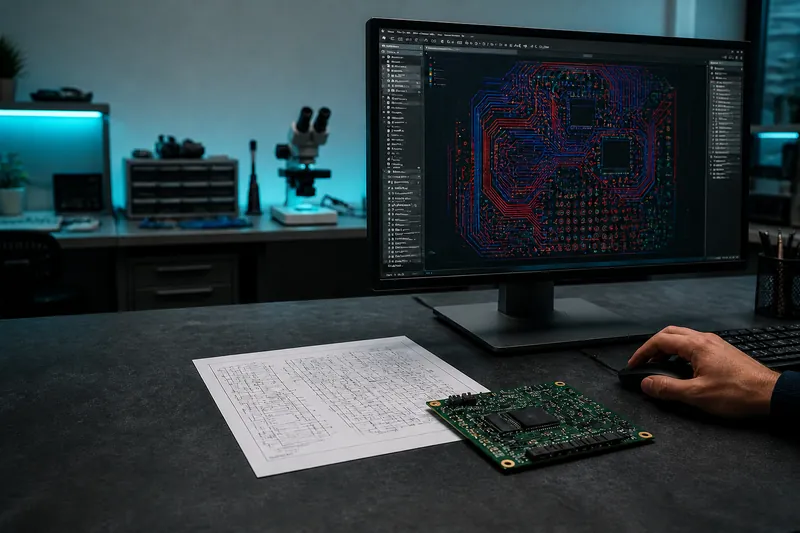
Manufacturing files as a controlled handover
Production preparation connects the tested prototype with an assembly that a partner can reproduce. A development folder may contain many useful files without showing which revision is final. We organise an approved package in which board data, components, assembly and testing describe the same device state. The aim is clear instructions rather than an archive that requires the supplier to reconstruct development history.
We first define the delivery goal: bare boards, assembled panels or programmed and tested units. Each needs different information. Available sources, the validated setup and the partner’s requirements determine what is missing. We do not assume that the same export list suits every order simply because the projects use similar design software.
Documentation can be requested separately for an existing design. We review the available material and distinguish unresolved changes from released information. That separation prevents a development draft from becoming a production instruction merely because it was the newest file in a shared folder.
Gerber and drill data for fabrication
Gerber files communicate board layers, while drill data describes holes. The outline and process requirements must also be unambiguous. We inspect the exported files independently to check that the intended layers and markings are present. A filename or a correct view in the layout editor does not establish what the released export actually contains.
The technical description records stackup, material and thickness requirements, with any agreed special conditions. Holes and mechanical features are compared with the board’s use. The partner can then distinguish fixed requirements from questions needing clarification instead of inferring intent from an incomplete drawing or an earlier conversation.
Files come from the same approved revision. A design change triggers a coordinated update of the exports. The order package remains identifiable later, making it possible to establish which information was used for a particular board and which modifications were introduced only after that build.
BOM, placement data and assembly drawings
The BOM identifies components and references with exact ordering information. The CPL provides positions, sides and rotations. Assembly drawings support interpretation and capture instructions that a table cannot show. Variant-dependent and deliberately unpopulated positions are marked explicitly so the partner can distinguish them from missing or inconsistent information.
References are checked across documents. Removing or replacing a component can affect the schematic, parts list and placement file together. Substitutes receive technical approval because a different package or electrical interface can influence firmware as well as the PCB. Sourcing queries therefore have a defined route back to engineering decisions.
Assembly instructions may also cover cables, separately connected parts and mechanical details. We state the partner’s task and expected delivery condition. This turns the package into usable instructions rather than a collection of files exported from a design tool without an explanation of how they fit together.
DFM and assembly review
Design for manufacture examines the board against the selected partner’s process capabilities. Holes, clearances, outlines and layer data are reviewed. Assembly considerations include packages, orientations, access and placement. The purpose is to identify questions before release, while changes can still be made deliberately and reflected in all related information.
A supplier query is considered in relation to design intent. We assess whether a proposal changes operation, mechanics or testing. Where it does, the affected details need approval together. A new complete package is then generated from the revised sources, replacing the earlier release for the intended order rather than leaving competing instructions in circulation.
Manufacturability review and functional verification answer different questions. Correct process data does not demonstrate that firmware and sensors work together. Records distinguish completed checks from evidence that still needs to come from the physical prototype or another assessment appropriate to the intended application.
Firmware, programming and test instructions
Programmed hardware needs a defined software revision, upload method and required settings. Compiled images and editable source are identified separately. If units receive individual parameters, the instructions explain how those relate to the shared software. This keeps device setup from being confused with a change to the program itself during assembly.
The test procedure states the connections, inputs and observations required. It can cover power, sensing, communication and outputs. Acceptance criteria follow the device’s purpose, with an indication of where results are recorded. Later units can then be assessed against the same requirement rather than whatever a particular operator remembers from the original prototype.
Functional test documentation does not promise certification. Additional assessments are discussed for the application. The production package establishes which assembly should be built, which program belongs on it and how the agreed checks are performed, preserving a useful boundary between manufacturing acceptance and wider product qualification.
Partner delivery and maintaining the package
PCB fabrication and batch component assembly take place exclusively at production partners. Files can be delivered to you or your chosen supplier, or we can coordinate ordering. pcbform handles technical preparation and result checking within the agreed scope. Partner selection follows project requirements and quantity rather than a named manufacturer assumed suitable for every job.
Send editable schematics, layout sources, component details and existing exports. Explain what has been built, which changes were made on the prototype and which setup should be manufactured. We list missing material so the preparation scope and outstanding decisions are visible before the package is treated as ready for release.
At handover, the file list, revision identifier and known notes describe the package together. Further changes produce another release from that baseline. Earlier versions can remain available for traceability while being clearly distinguished from the setup approved for the current order. That distinction supports repeat orders and later engineering work.
Related services and practical guides
Frequently asked questions
Are Gerber files sufficient for assembly?
No. A BOM identifies components, placement data defines their positions and assembly instructions clarify additional details. We select the required information around the actual board and production partner rather than assuming one file format covers the complete task.
Can you document an existing design?
Yes. We review sources and exports, then identify missing information. Data already suitable for production does not need recreating without reason, but its consistency with the rest of the released package still needs checking.
Does DFM mean functional testing?
No. DFM concerns process suitability. Circuit operation is examined separately after assembly and programming. The findings support different conclusions and are recorded accordingly rather than being presented as interchangeable evidence.
Must production be ordered through pcbform?
No. The agreed package can be sent to your own partner. Sharing that manufacturer’s requirements before preparation helps ensure that the documents fit the intended process and avoid unnecessary conversion later.
What happens when a component changes?
We assess the engineering impact and update the affected drawings, lists, placement information and software where needed. A new release identifies the revised package and preserves the reason for the change for future work.
Are editable sources included?
Source documents and production exports are specified separately. Formats and usage terms are agreed so the delivery is useful for its intended purpose and the basis for later changes is clear to everyone involved.
Tell us about your electronics project
Describe the task and share any available drawings.